Ask a client what they want from a lift and they will describe the cabin. Ask a contractor, and they will describe the shaft. The decision that actually governs both — and the project timeline, the structural drawings, and the electrical load — is the drive system, and it is usually settled last when it should be settled first.
For anyone specifying home elevators in residential work, particularly retrofits, here is how the four available mechanisms compare on the criteria that determine buildability.
Hydraulic drive
- How it works: A pump forces oil into a cylinder, extending a ram that raises the cabin either directly or via a roped arrangement. Descent is gravity-assisted, with oil bleeding back through a control valve.
- Space and structural demands: A pit beneath the lowest served level, typically substantial. A separate machine room housing the pump unit, oil reservoir, and controller — this can sit remotely, which is occasionally useful. A guided shaft, though load-bearing demands are lower than traction because the load transfers to the pit floor rather than the overhead.
- Where it fits: Heavier loads, short travel, projects where the pit can be excavated during construction. Ride quality is excellent, and the mechanism is forgiving of irregular use.
- Where it fails: Retrofits on slab-on-grade construction. Excavating a pit through an existing foundation is where budgets die. Oil temperature management also matters in warm climates — under repeated use, the fluid heats, and without cooling, the controller will lock the lift out.
Traction drive
- How it works: A motor drives a sheave; steel ropes or coated belts pass over it, cabin on one side, counterweight on the other. The counterweight offsets most of the cabin mass, so the motor only manages the difference.
- Space and structural demands: The most demanding of the four. A pit, a structural shaft rated for the full suspended load, and overhead headroom for the machine and safety clearances. Machine-room-less variants tuck the motor into the shaft head, which helps, but the headroom requirement remains.
- Where it fits: New construction with multiple stops and frequent use. Energy efficiency is the best of the four over long travel, and modern regenerative drives return braking energy to the supply.
- Where it fails: Almost any retrofit. The overhead requirement alone typically rules it out in an existing house with standard floor-to-floor heights, before you reach the question of shaft construction.
- Screw drive
- How it works: A threaded steel column runs the height of travel; a driven nut assembly on the cabin climbs it. Because the cabin cannot free-fall on an intact screw, the mechanism is inherently self-arresting.
- Space and structural demands: No pit in most configurations, no separate machine room, and the column is often self-supporting. This makes it markedly more retrofit-friendly than the first two.
- Where it fits: Small-footprint installations where simplicity and inherent fall protection are priorities.
- Where it fails: Speed is the lowest of the four — noticeably slow over three or more stops. The screw requires periodic lubrication and generates audible mechanical noise, which is a genuine consideration when the lift sits in a living room rather than a service core.
Pneumatic vacuum drive
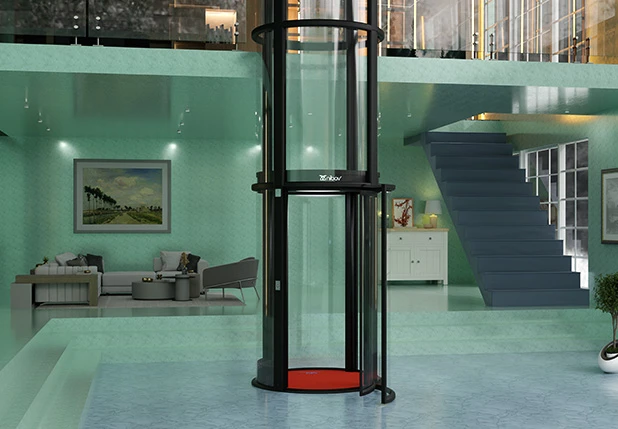
- How it works: The cabin sits inside a sealed transparent cylinder. Turbines at the head of the cylinder reduce air pressure above the cabin; the higher pressure below pushes it upward. Descent is controlled by regulating air back into the upper chamber — gravity does the work, so descent draws almost no power.
- Space and structural demands: The lowest of the four. The cylinder is the shaft, so no separate enclosure is built. No pit, no machine room, no counterweight, no hydraulic fluid. The assembly is self-supporting and bears on the existing floor slab rather than requiring load-bearing walls, which is the property that opens up retrofit work.
- Where it fits: Existing homes. Stairwell voids, living-room corners, external bays. Installation is measured in days because there is almost no wet trade involved. Manufacturers including Nibav Lifts have concentrated on this segment, supplying panoramic-cabin units sized for two to three passengers in Indian and international residential markets.
- Where it fails: Capacity is the constraint — these are passenger lifts, not goods lifts, and payload ceilings are lower than hydraulic equivalents. Travel height is bounded by practical cylinder length. The turbines are audible during ascent, though descent is near-silent since the turbines are not running.
Comparison at a glance
| Feature |
Hydraulic
|
Traction
|
Screw
|
Pneumatic
|
|
Pit required
|
Yes
|
Yes
|
Usually no
|
No
|
|
Machine room
|
Yes
|
Yes / MRL
|
No
|
No
|
|
Structural shaft
|
Yes
|
Yes
|
Minimal
|
None
|
|
Load path
|
Pit floor
|
Overhead
|
Column base
|
Floor slab
|
|
Retrofit suitability
|
Poor
|
Very poor
|
Good
|
Excellent
|
|
Install duration
|
Weeks
|
Weeks
|
Days
|
Days
|
|
Capacity
|
High
|
High
|
Moderate
|
Lower
|
|
Speed
|
Good
|
Best
|
Slowest
|
Moderate
|
Design considerations that get overlooked
Load path, not just footprint. A self-supporting unit still delivers its full mass plus dynamic load to a specific area of the slab. Get the reaction figures from the manufacturer and have them checked, particularly on cantilevered or older slabs. Power supply reality. Single-phase compatibility determines whether a lift works in most Indian homes without a supply upgrade. Ask for starting current, not just running current — inverter and generator sizing depends on the inrush. Acoustic planning. A lift placed adjacent to a bedroom wall will be heard. Where the mechanism generates noise on the drive stroke, favour a location off circulation space rather than sleeping areas.
Thermal load. Glass cabins in a sunlit atrium gain heat. Consider orientation and any adjacent glazing. Client-facing detail. Threshold levelness at every landing, door swing clearance against existing furniture layouts, and how the cabin reads within the room. In an open-plan living area, a transparent cylinder becomes a visual object whether you intend it or not — treat it as one.
Specifying well
Sequence the decision properly. Establish the site constraints first — floor-to-floor heights, slab condition, available headroom, power supply. Those constraints will usually eliminate two of the four drive systems immediately. Only then discuss capacity, cabin and finish.
Request the manufacturer's structural reaction data, the compliance standard the unit is certified to, the emergency descent behaviour on power loss, and a spare-parts availability commitment. And where possible, put the client in a working unit before the drawings are finalised. Their reaction to the ride is information you cannot get any other way.